 Bankzilla
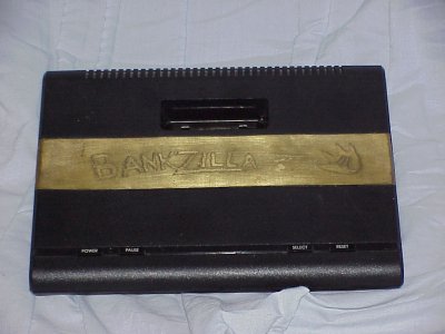
This is one of my biggest projects I've ever undertaken. Bankzilla
consists of 50 chips fitted onto two double-sided circuit boards, crammed
into an Atari 7800 console case. On the outside, it looks no different
than a regular old 7800. But when you turn it on, it's quite obvious this
is no ordinary console!
What it is:
Bankzilla is a complete all-in-one Atari 2600 with every game I can get ahold of
crammed inside. The game is selected via an on-screen menu using the joystick.
So far, I have managed to accumulate 838 different ROMs, including many prototypes
and demo games. The LED on the front lights up different colours to indicate which
controller should be used to play the currently-selected game.
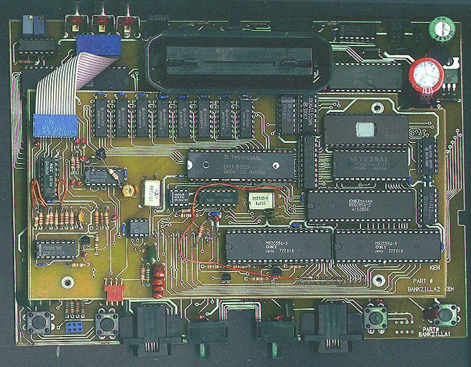
The Guts!
 Both Bankzilla boards connected
Bankzilla's bottom board outline
Bankzilla's top board outline
How it works:
Bankzilla consists of many sub-units:
2600 Core
Bankswitch Emulation Core
ROM Image Storage
Joypad Interface
User Controls/Feedback
Video/Audio Sub-systems
System Control
Power Supplies
2600 Core
As you might imagine, the 2600 core isn't anything special- just the
standard three chips- 6507, TIA, and 6532. It connects directly to the
cart port in exactly the same way it does on any 2600. Since the 2600's
cart port has two ground pins, one may be lifted and used to check for the
presence of a cartridge. Pulling it up to +5V will show low if a cart is
inserted, and high if removed. Bankzilla uses this to detect external
carts. I've tested all 400 carts in my collection to see if both ground
pins are connected internally. In all cases they were. I'm pretty certain
then that this can be used without problems.
Bankswitch emulation core
This is the most complex part of Bankzilla, and took most of the development
effort. It consists of just three chips- an
FPGA, 74LS170 4*4 register
file (aka a 16-bit dual-ported RAM), and a 74LS31 Hex Delay Element (this
is used as a one-shot; a falling edge on the input will result in a very
narrow pulse on the output which is used to write to the 74LS170. Rising
edges on the input produce no output pulses). There are three other chips
in this system which connect between the emulation core and the 2600 core-
these are a 6264 8K*8 RAM, the Supercharger chip, and the Pitfall ][ chip.
The 8K*8 RAM is used for RAM Plus (256 bytes), Superchip (128 bytes),
M-Network (1K), and Supercharger RAM (6K). The Supercharger chip is taken
direct from a supercharger- it's a 40-pin device which sits on the 2600's
address/data bus. It's outputs which select RAM and ROM connect to the
bankswitch emulation core so that it can select the proper RAM bank, ROM, etc.
The Pitfall ][ chip is similar- it's single input and output connect here
too.
ROM Image Storage
This is simply 8 1Mbyte 32-pin 27C8001 EPROMs. Connected to these is one
74HC138 1-of-8 selector. Connected to the '138s positive enable line is
the cartridge sense line talked about in the 2600 Core section. When a cart
is inserted, it disables the '138, thereby disabling all internal ROM.
The ROMs are broken up into 32K chunks which are acted upon by the bankswitch
emulation core. Since there are a total of 8 ROMs, and each has 32 banks,
that makes a total of 256 32K banks which may hold any combination of ROM
images (i.e. 4K, 8K, 2K, etc). I recently hacked this area a bit to allow
the Megaboy ROM image to work which is 64K. I routed A15 through the FPGA.
during normal operation, it is passed through un-changed. However, when
the Megaboy ROM image is selected, it becomes the high order address line
for this ROM image. It's a definate hack, but it works. The only
"gotcha" is that this ROM image takes up two 32K slots, and it must be on
an even boundry, but this isn't too hard to take into account.
Joypad Interface
Bankzilla can even use NES/SNES joypads un-modified! I like joypads
better than joysticks. Mainly because I don't have indestructable hands
like I used to when I was small. I can use joypads without stress on my
hands. It's pretty simple- joyport #1 connects to two joypads via an
adapter cable. Inside Bankzilla is a PIC16C55 28-pin microcontroller which
checks the joystick inputs periodically to determine wether a stock stick
or NES joypad is present and takes action accordingly. The PIC16C55
works in conjunction with a 4066 quad analog switch which switches in the
2600 stick, or lets it go only to the PIC. This makes sure joypad reading
does not interfere with 2600 joystick response. When a joypad is connected,
the user now has control over the Select and Reset buttons by pressing the
Select and Start buttons on the pad, respectively.
User Controls/Feedback
This is the multicolour LED, and front panel buttons. The multicolour LED
replaces the normal power LED. It consists of red, green, and blue LED chips
all in one white case. Therefore, it can light up most any colour. It tells
the user which type of controller to use:
Blue- Joysticks
Green- Paddles
Red- Keypads
Yellow- Driving Controllers
Purple- Paddles and Stick
Aqua- Stick/Pad (Star Raiders)
White- Light Gun
Black- Unknown/Other
When you are in the menu mode, it cycles through all of the above colours
very quickly.
The power button is soft. That is, it does not necessarally turn
power on or off. If the unit is off, pressing it turns the unit on. If
you press it while on the menu screen, it turns the unit off; while
in a game, pressing the button brings back the menu. The Pause button really
runs the TV Type selection, as it does on the 7800. However, it's now a
toggle. The PIC16C55 performs this toggling. The power LED will flash indicating
the state:
black white
black white
- indicates B/W mode, and
red green
blue
- indicates Colour mode.
Video/Audio Subsystems
These consist of the 2600's video output circuitry, the TMS9918a video
chip used to generate the menu, 2600 audio muting, and stereo/mono audio
control. The 2600 output circuitry is fairly complicated; it has a 4050
hex buffer to buffer the luminance and synch signals, a resistor ladder
to generate the proper video brightness, some mixing resistors to mix the
final luminance output with the synch and colour burst information. This
is fed to a video buffer (single transistor), and is then connected to
one input of a video switch. The other input of the video switch connects
to the TMS9918a's video output. A 4066 selects one of two colour reference
voltages to compensate for NTSC/PAL. Another 4066 is used to both mute the
2600's output (when showing the menu) and to short the two outputs together
for mono audio.
System Control
This pieces together all the above sub systems into one unit. It's an
80C85 8-bit processor running at 8Mhz with 512K of EPROM, 32K of RAM,
two 82C55's providing 48 I/O lines, TMS9918a video chip, and 256 byte
EEPROM for user setting storage. The EPROM stores the menu programming,
game list, Supercharger data, and FPGA fusemap. Said fusemap is used to
program the FPGA on startup. This tells the FPGA how to connect it's internal
gates into an arrangement useful by the rest of the system. The Supercharger
data is stored in 8K blocks- both the actual game code and sumcheck/header
information is stored. When a Supercharger load is played, the 80C85
actually generates the audio the Supercharger requires to work! This is
accomplished by a 100% cycle-counted program.
Power Supplies
|


