Continuing on....
Step 11
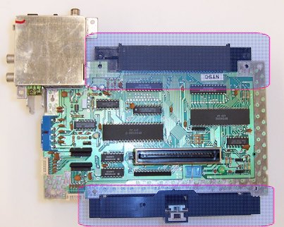
[ ] Remove the cart basket by pulling it forward away from the connector.
    It has a lip that fits over the bottom of the board to keep it in place.
Step 12
[ ] CAREFULLY CAREFULLY remove the CPU. This is probably the trickiest part
of the whole operation. You must NOT DAMAGE THE BOARD or else it will
not work. I use a desoldering station with good results, but for
"improvised" methods, solder braid, desoldering pumps, etc. can be used.
DO NOT pry the chip off the board, as this can/will break pins and rip
the through-holes out! After desoldering, gently push on the pins with a
flat-blade screwdriver to break them away from the edges of the holes, and
or rock the chip carefully back and forth to help loosen the bond between
the pin and inner wall of the hole. If you rip out the through holes, it
will render your NES dead as a doornail. In extreme circumstances, you could
maybe cut the CPU out and remove each pin and then vacuum out (with a solder
sucker) or wick out the holes, then obtain a new CPU somehow... maybe from a
Playchoice 10 board or similar.
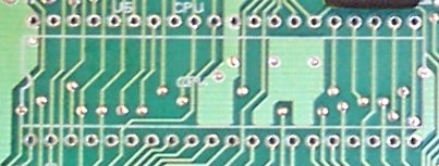
[ ] CAREFULLY remove C8. Note that this part number MIGHT change- I do not know
if it's the same on all revisions of the NES board. It is connected to pin 7
of the lockout chip in any event, and is a .1uf disc capacitor.
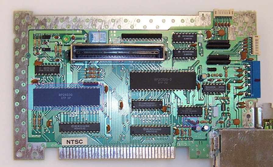
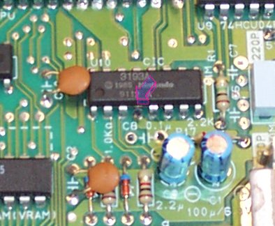
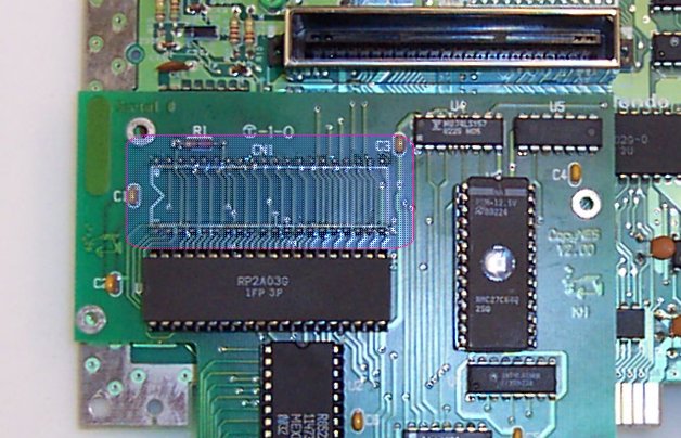
Removed CPU
It should look like this when the CPU is removed.

Step 13
[ ] Carefully bend the highlighted caps over flat against the PCB so they clear when
    the CopyNES board is installed.
Step 14
[ ] Cut pin 4 of the lockout chip to disable it. (see below)

Note that the caps are now laying flat on the board.
Step 15
Closeup of where pin 4 is.  In the picture it has been cut.  I cut it with a
pair of fine wire cutters, then pushed it away from the chip.  Be careful since it
is kinda easy to break the package.  This isn't detremental, but it's not too good
prolly in the long term.
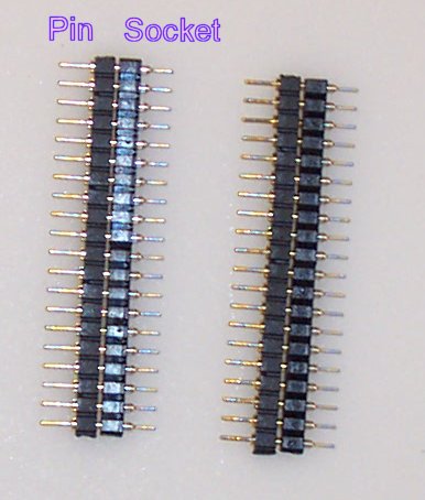
Step 16
[ ] Plug the pins and sockets together.  NOTE: The size of the pin on either end is
    NOT THE SAME.  One side will have slightly smaller diameter pins than the other.
	Plug the smaller diameter pins into the matching sockets.
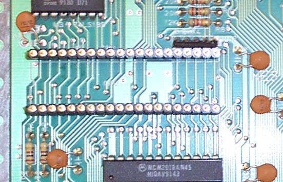
Step 17
[ ] Drop the connected together sockets onto the board. Make sure you put the socket
    end onto the NES board, and have the pins end up!  This will let you plug the
	CPU directly into the NES board to test it in case something doesn't work.
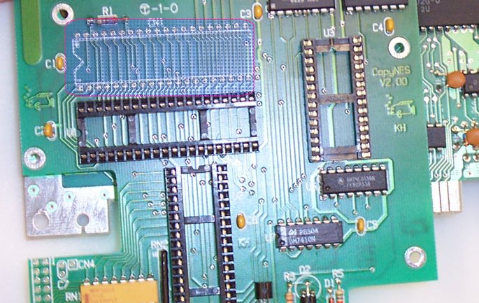
Step 18
[ ] Sit the CopyNES board on top and make sure the pins go through the holes.  Look
    on the side to make sure it all lines up right.  Now tack the 4 corners on the top
	of the CopyNES board, and on the bottom of the NES board.  Be sure to push the two
	boards together with your fingers while you do this!  THE TWO BOARDS MUST BE AS CLOSE
	TOGETHER AS POSSIBLE.  Otherwise, the board may not fit into your NES case!!
Step 19
[ ] After tacking, solder all the pins on the bottom of the NES board.
Step 20
[ ] Then turn it over and solder all the pins on the top of the CopyNES board.