1992 11 in 1 Ball Series
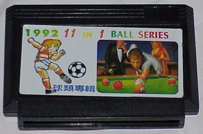
Cartridge Front
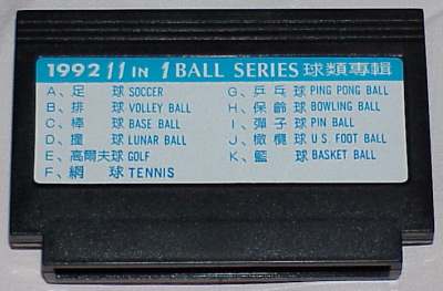
Cartridge Back
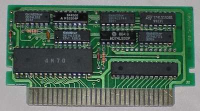
Cartridge Board
What Is It?
The world's Nastiest Multicart. The circuit on this thing is a technical nightmare! This cart took the most work to RE due to the very complex
and convoluted logic of its circuit.
The Games:
(See cartridge back)
The Tech:
A bunch of TTL "glue" logic, a ROM, and a VRAM chip. The logic was pretty messed up and must've been designed by someone high on crack.
There's plenty of "MML" logic (Mickey Mouse Logic), and lots of edge-triggered nonsense.
------------------------------------------------------------------

This mapper has been assigned the number 51.  (that's 51 decimal)

Holy Fuck On a Popsicle Stick!  These carts keep getting worse!  This one
uses 7 logic chips, 1 VRAM, and a 512K PRG ROM.  The mapper is one of the
worst pieces of digital "design" I have seen to date.  If you have ever
tried to trace "Spaghetti Code"; this would be the hardware equivelant.


---


The hardware:

It consists of 7 TTL chips (7408, 7402, 7432 (2), 7474, 74153, 74161),
an 8K VRAM, and a 512K PRG ROM.  The banking is shall we say, "Fucked Up".
Mirroring is software selectable, as is alot of other stuff.

-

Writing to the 6000h-7FFFh area will set the Mapper Mode register, and
writing to 8000-FFFFh will set the bank select register.

-

Bank Select Register:

7  bit  0
---------
xxxx CCCC

bit 3 = MSB, bit 0 = LSB.  This is the bank select register- it selects
which 32K ROM bank will be used.  It is accessed by writing anywhere in the
8000h-FFFFh range.  There are no bus conflicts.

-

Mapper Mode:

7  bit  0
---------
xxxB xxAx

This set by writing anywhere in the 6000h-7FFFh range.  Only bits 4 and
1 are used.  Below is the effects on ROM addressing for the various modes.

-

Addressing layout for the ROM:

B,A:
----
0,0  -  Mode #0
0,1  -  Mode #1
1,0  -  Mode #2
1,1  -  Mode #3

-

Mode:

0  -  V mirroring
1  -  V mirroring
2  -  V mirroring
3  -  H mirroring

0  -  A14 passes through
1  -  A14 passes through
2  -  A14 is pulled high
3  -  A14 passes through

0  -  A15 = bank select bit #0 if A14 is low.  If A14 is high, A15 = 1
1  -  A15 = bank select bit #0
2  -  A15 = bank select bit #0 if A14 is low.  If A14 is high, A15 = 1
3  -  A15 = bank select bit #0

0  -  A16 = bank select bit #1 if A14 is low.  If A14 is high, A16 = 1
1  -  A16 = bank select bit #1
2  -  A16 = bank select bit #1 if A14 is low.  If A14 is high, A16 = 1
3  -  A16 = bank select bit #1

A17 always = bank select bit #2

A18 always = bank select bit #3 OR /A15

-

This setup is just assinine.  Obviously "tuned" for the set of games on
the cart.  The ROM is enabled from 6000h through FFFFh.  When you are
reading from the 6000h-7FFFh area, the bank select bit 3 is set to 1.
(that is the "bit #3 OR /A15" part, above)  Below is a piece of code
that implements this weird scheme.

-

In this code, "bank" is a 6 bit value which holds the desired 8K bank.
There are 64 8K banks then (8*64 = 512K, the size of the ROM).

"bank" = the final output bank select register.
"mode" = the mapper mode. (written to at 6000h-7FFFh)
"select" = the bank select register, (written to at 8000h-FFFFh)
"address" = the current address of the NES CPU.

-

if (address AND 4000h) = 0 then x = 0 else x = 001100b ;A14 determines mask
if mode = 1 or mode = 3 then x = 0

bank = select << 2     ;get the proper bank set up
bank = bank OR x       ;OR the mask with the bank to set bits if needed

if (address AND 8000h) = 0 then y = 100000b else y = 0 ;A15 determines mask

bank = bank OR y       ;OR the mask with the bank to set bit if needed

if mode = 2 then z = 000010b    ;if mode 2, pull A14 high

bank = bank OR z       ;OR the mask with the bank to set bit if needed


-

"bank" now holds the desired 8K bank #.
|