Here it is. Nintendo's largest mapper. Too bad it was so expensive compared to the others. The cost is most likely
what made developers shy away from it. It did come out a bit late in the game, but it appears cost was the determining
factor.
This chip has a very large set of functionality included in it- 1K of extra RAM for general use or attribute table use,
8*8 bit multiplier, extra sound channels, split screen scrolling, control for up to 64K of WRAM, battery backup control,
and some other goodies.
Ironically, Koei seemed to like this chip, and used it for many of their games... Most of the PCBs used were for Koei games.
Such a shame that their games seemed to totally waste the hardware resources.
Some of these MMC5 boards have the distinction of actually FILLING UP the entire cart shell, unlike most other boards.
Register description: to be finished
The Boards:
 NES-ELROM - Max. 512K PRG, 256K CHR. NES-ELROM - Max. 512K PRG, 256K CHR.
NES-ETROM - Max. 512K PRG, 256K CHR, 16K WRAM (8K batt-backed).
NES-EWROM - Max. 512K PRG, 256K CHR, 32K WRAM (batt-backed).
MMC5 Packaging Information
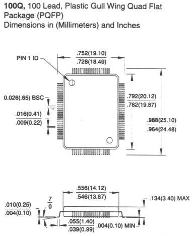
MMC5 comes in a 100 pin rectangular PQFP package.
MMC5 Pinout:


                           80              51
                            |              |
                           .----------------.
                        81-|                |-50
                           |      MMC5      |
                       100-|                |-31
                           \----------------'
                            |              |
                            1              30


Pin# Function      Pin# Function      Pin# Function      Pin# Function
---- --------      ---- --------      ---- --------      ---- --------

1  - Aud 1         26 - CHR A11 (n)   51 - PRG A6 (s)    76 - /WE (w)-all
2  - Aud 2         27 - CHR A12 (n)   52 - PRG A7 (s)    77 - NC
3  - Aud 3         28 - CHR A13 (n)   53 - PRG A8 (s)    78 - NC
4  - +5V           29 - NC            54 - PRG A9 (s)    79 - M2 (n)
5  - CHR A0 (s)    30 - NC            55 - PRG A10 (s)   80 - GND
6  - CHR A1 (s)    31 - CIRAM /CE (n) 56 - VCC of RAM (w)81 - NC
7  - CHR A2 (s)    32 - CIRAM A10 (n) 57 - +Vbatt        82 - NC
8  - CHR A3 (s)    33 - CHR /WR (n)   58 - PRG A11 (s)   83 - CE (w)-all
9  - CHR A4 (s)    34 - CHR /RD (s?)  59 - PRG A12 (s)   84 - CHR D0 (s)
10 - CHR A5 (s)    35 - /IRQ (n)      60 - PRG A13 (r)   85 - CHR D1 (s)
11 - CHR A6 (s)    36 - PRG D0 (s)    61 - PRG A14 (r)   86 - CHR D2 (s)
12 - CHR A7 (s)    37 - PRG D1 (s)    62 - PRG A15 (r)   87 - CHR D3 (s)
13 - CHR A8 (s)    38 - PRG D2 (s)    63 - PRG A16 (r)   88 - CHR D4 (s)
14 - CHR A9 (s)    39 - PRG D3 (s)    64 - PRG A17 (r)   89 - CHR D5 (s)
15 - CHR A10 (r)   40 - PRG D4 (s)    65 - PRG A18 (r)   90 - CHR D6 (s)
16 - CHR A11 (r)   41 - PRG D5 (s)    66 - PRG A19 (r)   91 - CHR D7 (s)
17 - CHR A12 (r)   42 - PRG D6 (s)    67 - PRG A13 (n)   92 - NC
18 - CHR A13 (r)   43 - PRG D7 (s)    68 - PRG A14 (n)   93 - NC
19 - CHR A14 (r)   44 - +5V           69 - A13 (w)-all   94 - CHR A0 (r) *2
20 - CHR A15 (r)   45 - PRG A0 (s)    70 - A14 (w)-all   95 - CHR A1 (r) *2
21 - CHR A16 (r)   46 - PRG A1 (s)    71 - /CE (w)-0     96 - CHR A2 (r) *2
22 - CHR A17 (r)   47 - PRG A2 (s)    72 - /CE (w)-1     97 - CL3 *2
23 - CHR A18 (r)   48 - PRG A3 (s)    73 - NC            98 - SL3 *2
24 - CHR A19 (r)   49 - PRG A4 (s)    74 - PRG /CE (r)   99 - GND
25 - CHR A10 (n)   50 - PRG A5 (s)    75 - NC           100 - Aud 4

(r) - this pin connects to the ROM chips only
(n) - this pin connects to the NES connector only
(s) - this pin is shared with the NES connector and ROM chips
(w) - this pin connects to the WRAM only

Notes:

Audx pins are for the audio circuitry.  Said circuitry is on the PCB for audio, even though
the NES cannot accept it.  A small jumper plug could've been fashioned, however, to pass
the signal through on the expansion port.  Otherwise, it's as useless as tits on a bull.

*2: PINS 94 thru 98. These set the cart in either SL or CL mode.  I have no
clue what the diffrence between the two modes are; the cart I checked
(Castlevania 3) was set to CL mode.

To set to CL mode:

Connect CHR A0 from the NES to A0 on the CHR ROM.
Connect CHR A1 from the NES to A1 on the CHR ROM.
Connect CHR A2 from the NES to A2 on the CHR ROM.
Connect pins 97 and 98 together.
Leave pins 94,95 & 96 floating on the MMC5


To set to SL mode:

Connect pin 94 of the MMC5 to A0 of the CHR ROM.
Connect pin 95 of the MMC5 to A1 of the CHR ROM.
Connect pin 96 of the MMC5 to A2 of the CHR ROM.
Connect pin 98 to ground.
Leave pin 97 floating.


These modes control the operation of the split screen scrolling.  When in SL mode, the split
screen scrolling can be used.  When in CL mode, it is bypassed.  Why you cannot keep the MMC5
in split screen mode at all times may have something to do with other functionality it can
perform.  More testing may be required.
|