Here's how you assemble a CopyNES. Before you begin, check to make sure all parts are included in the kit,
or if you bought just the PCB, make sure you have obtained all required parts. Here is the parts list:
(1) 270 ohm resistor, 1/4W 5%
(1) 1.3K ohm resistor, 1/4W 5%
(1) 2.2K ohm resistor, 1/4W 5%
(1) 10K ohm resistor, 1/4W 5%
(1) 56K ohm resistor, 1/4W 5%
(6) 0.1uF monolythic capacitor, .1" lead spacing
(1) 1uF monolythic capacitor or polarized electrolytic
(1) 1N4148 diode
(1) 2N4401 NPN transistor
(1) 2N4403 PNP transistor
(1) 100 ohm, 8 resistor 16 pin network
(1) 4.7K, 9 resistor 10 pin network
(1) 74LS10
(1) 74LS138
(1) 74LS157
(1) 74LS32
(1) 6522 port chip
(2) 40 pin socket
(1) 28 pin socket
(1) pre-programmed EPROM
(1) 40 pin DIP dual ended header with round pins
(2) 20 pin SIP female machine sockets (or 4 10 pin units)
(1) 26 pin 2 row by 13 square pin header
(1) 26 pin IDC connector
(1) 25 pin female DB-25 IDC connector
(1) 8" of 25 pin ribbon cable
(1) 6 foot male DB-25 to male DB-25 straight through cable
Once you have obtained all the parts and/or checked the list to make sure everything is present, then you're ready
to start assembling. Please proceed only in the order shown! This should prevent problems later. Some things should
be done in a certain order, and be sure to READ CAREFULLY for caveats or pitfalls!
Note: In these pictures, I have shown how to use the Digikey 64 pin dual ended header (cut down from 64 pins into
two 20 pin strips). At the time of writing I did not have the 40 pin headers. Click .here. for info on the 40
pin header that I am selling and that is included with the kit.
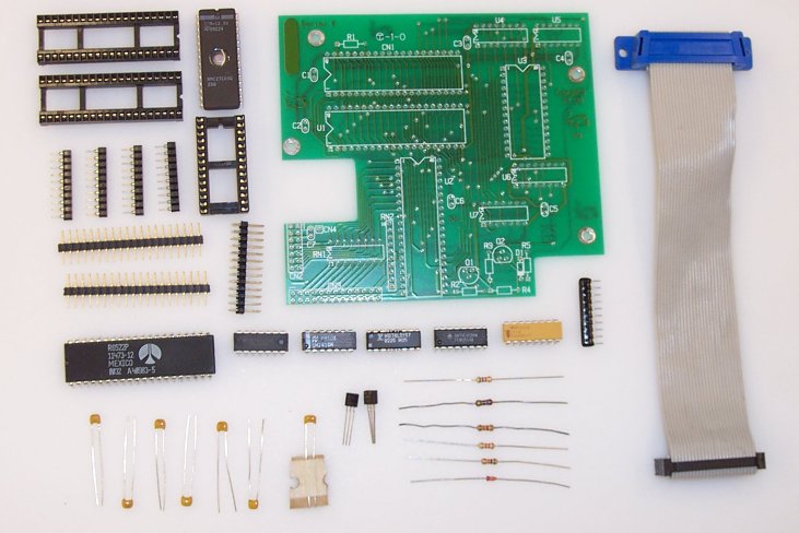
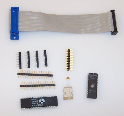
Complete kit contents
Hopefully, you have all these parts shown. Once you do, it is time to begin!
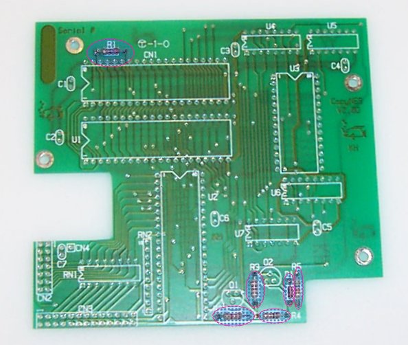
Step 1
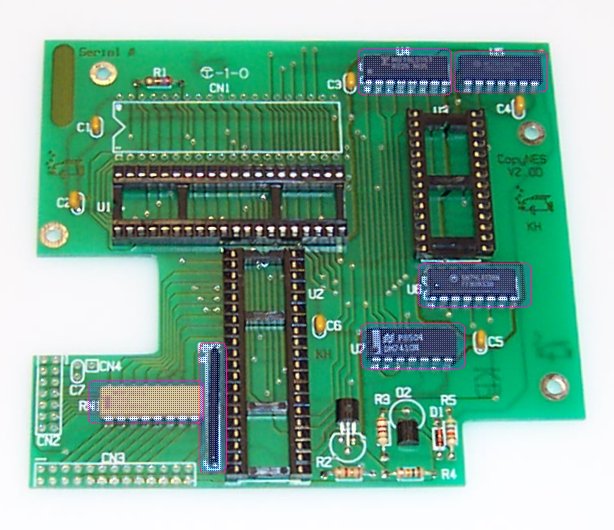
[ ] Install R1 - 270 ohms (red, purple, brown, gold)
[ ] Install R2 - 1.3K ohms (brown, orange, red, gold)
[ ] Install R3 - 2.2K ohms (red, red, red, gold)
[ ] Install R4 - 10K ohms (brown, black, orange, gold)
[ ] Install R5 - 56K ohms (green, blue, orange, gold)
[ ] Install D1 - 1N4148.  Observe polarity! The band on the diode and PCB should match
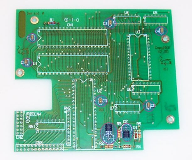
Step 2
Note: Make sure you use the proper capacitors!  They are marked "104".
You will have 1 capacitor extra, which is marked "105".  This extra cap is
on a paper carrier so it should be easy to tell it apart.  This capacitor
will be used in step 22!

[ ] Install C1 through C6 - 0.1uF (marked 104)
[ ] Install Q1 - 2N4403 (Flat side of transistor should match PCB outline, lay it flat on the board)
[ ] Install Q2 - 2N4401 (Flat side of transistor should match PCB outline, lay it flat on the board)
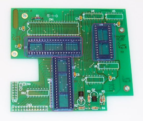
Step 3
[ ] Install a 40 pin socket at U1 (observe polarity! Line up socket notch w/ PCB outline)
[ ] Install a 40 pin socket at U2 (observe polarity! Line up socket notch w/ PCB outline)
[ ] Install a 28 pin socket at U3 (observe polarity! Line up socket notch w/ PCB outline)
Step 4
[ ] Install U4 - 74x157 (74LS157, 74157, 74HC157 etc) Observe polarity!
[ ] Install U5 - 74x32  (74LS32, 7432, 74HC32 etc)    Observe polarity!
[ ] Install U6 - 74x138 (74LS138, 74138, 74HC138 etc) Observe polarity!
[ ] Install U7 - 74x10  (74LS10, 7410, 74HC10 etc)    Observe polarity!
[ ] Install RN1 - 100 ohm resistor network (marked 101G, yellow, 16 pins)
[ ] Install RN2 - 4.7K ohm resistor network (marked 472G.  Make sure
    dot on the resistor network lines up with the small "1" marking on PCB!
Step 5
You should have these parts left.  No more, no less!

Note: the capacitor  you have left over is a 1uF monolythic cap.  It is
the only cap on the paper tape, and is marked "105".
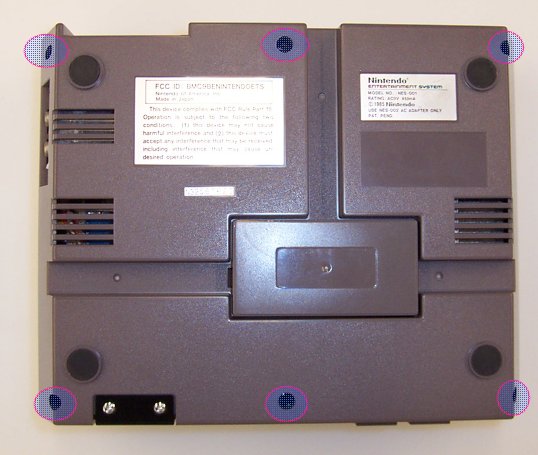
Step 6
Time to crack open the NES!  Make sure the NES works first before continuing.

[ ] Remove the 6 screws indicated on the picture, Then remove the top.
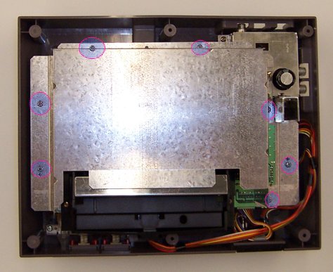
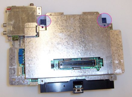
Step 7
[ ] Remove the 7 screws indicated on the picture. Remove the top metal shield
    and throw it away.
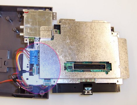
Step 8
[ ] Remove the 6 indicated screws.  Note that 2 are silver.  These screws are
    longer than the rest.
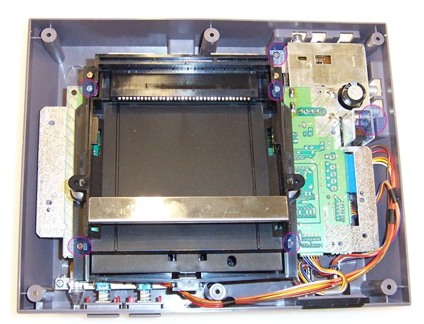
Step 9
[ ] Remove the PCB and flip it over, then unplug the 3 connectors.  Be sure to grab them
    on the CONNECTOR and do not pull off using the wires or else the connectors may break.
Step 10
[ ] Remove the last 2 screws holding the cart basket to the cart connector.
[ ] Remove the bottom metal shield and throw it away.