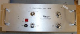
ML-1 Brown Board
Part Number 1507
|
Status: Totally depotted, EPROM dumped, circuit traced out, schematic generated, restuffed and working. There is a single 2704 EPROM on the board. Here's the ROM.
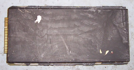
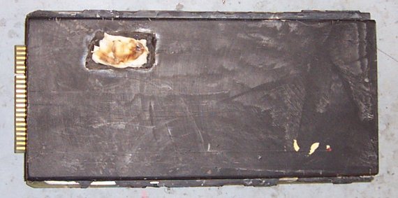
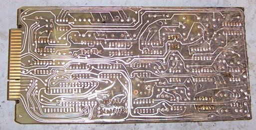
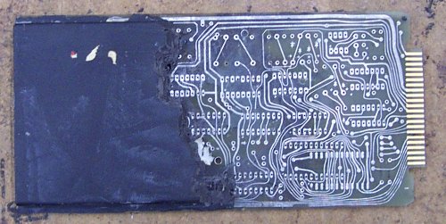
Here's the top before I started work depotting it. The white is RTV silicone covering the EPROM and probably a diode (in the other visible part). The board weighs in at around 14 ounces when fully potted.
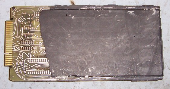
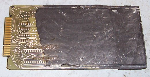
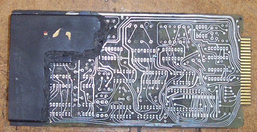
And the bottom, showing how they didn't fully fill this side. Apparently they didn't think it was important. However, I could see the legs of the EPROM before I took off the potting shell. I chose this one to de-pot since it has the EPROM in it.
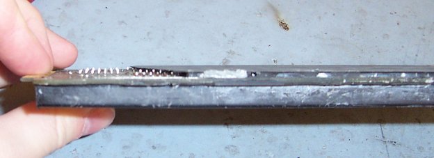
And a side view. It is almost exactly .5" thick. I measured it with a micrometer and it's only a few mils shy of .5"
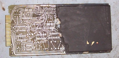
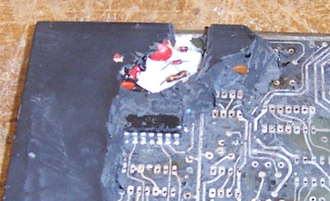
I have removed the potting down to the top of the EPROM. I left the chunk of RTV on so that the flash won't dork up the EPROM. I'm sure it wouldn't hurt the programming on it, but I'm not taking any chances with an EPROM that has 26 year old data on it.
Bottom view. I have removed the potting around the EPROM pins so that I can solder wires on. Unfortunately, I forgot to take pics of my EPROM "rig", but it's the same one I used on the Votrax Personal Speech System, so if you want to see what it looks like, you can see it there. I was very careful to dump the EPROM in situ so that the heat of un-potting it wouldn't erase its programming. After I dumped it twice using different EPROM programmers and verifying, I carefully de-potted it and it went onto the next stage.
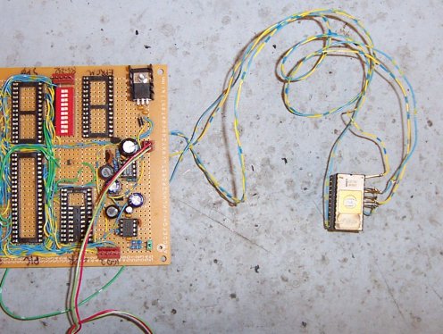
This is my special EPROM socket I made. It's just a wirewrap socket with some pins bent up, but it is going to a board supplying 5V, 12V, and -5V to run the EPROM. It needs those three voltages in order to work, and no EPROM programmers made since probably 1985 support three voltages. The socket goes into the EPROM programmer like normal, and I plug a wall wart into the power supply which does its thing. I dumped the ROM on two different programmers before and after de-potting to make sure things were good. The data matched in all cases.
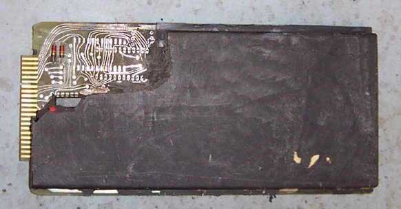
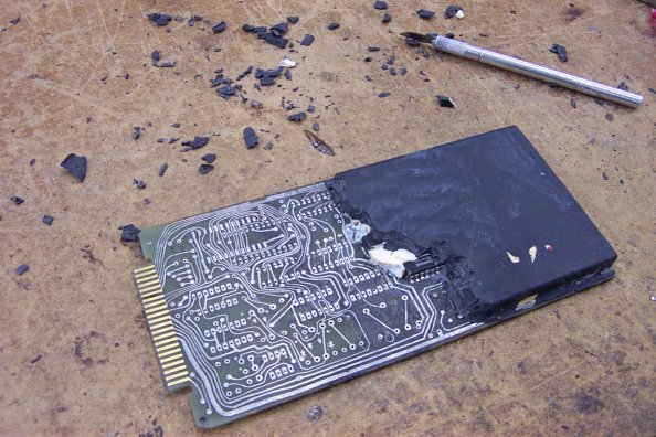
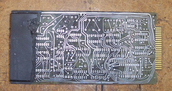
And there's the empty EPROM spot on the board after I de-potted it. For some reason, the epoxy wasn't sticking too well to the board- almost like there's a flux residue on it. This coupled with the lack of parts on this section of the board made it easy to remove huge chunks almost 1/2" on a side and the entire thickness of the potting.
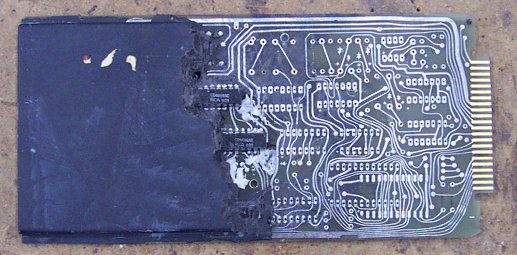
And here's the bottom after fully de-potting it. At this point the board weighs 12 ounces. Like the top, the potting was fairly easy to remove, but the farther down the board I went towards what would be the bottom of the potting shell, it got progressively harder and harder. It seems the pressure of the potting compound makes it bond better to the board material. Also, three of the chips have been worked on before this was potted. There's flux and such around the pins, and two places where routes were cut and then patched up again with part leads soldered on. Obviously someone was fishing for the problems and then fixed them before potting it up.
De-potting continues. The EPROM and half of the parts have been removed so far. The entire digital section is gone, as is the triangle wave generator for the PWM reconstruction circuitry. Some chips and a couple blobs of white RTV silicon are peeking through the active front (where I am actively de-potting).
More epoxy has been removed. You can see most of the RTV now. Votrax always covered up the diodes and EPROMs with RTV before potting... probably because they didn't want them to break when the epoxy cured. The knife I use to de-pot can be seen, as well as some of the swarf.
Two chips have been fully uncovered down to the pads on the board. They are ready to come out now. Most of the RTV has been scraped away from the board and the diodes were removed. To remove the RTV from the board, I use a Scotchbrite(tm) pad. It scrapes it all away without damaging anything.
The chips have been removed from the board, and the area cleaned up of any stray potting.
At this point, I have removed almost everything, and the very difficult section is left with a lot of capacitors and what I later find out is the +8V and -8V regulator. The RTV is hiding two diodes, and there's some large 10uF tantalum caps present.
I have broken the epoxy off around the RTV and you can see inside after I removed some of it. A 100pf ceramic disc capacitor can be seen poking up from the epoxy, too.
And now I have removed all the RTV and the parts contained within, and cleaned up the board.
Continue here |
